In this chapter I present the 'ProofWidgets'In general software parlance, a widget is a graphical component from which to build GUIs. It can also sometimes mean a small piece of interactive user interface that is embedded in another application, for example iPhone widgets. framework for implementing general user interfaces within an interactive theorem prover. The framework uses web technology and functional reactive programming (FRP), as well as the metaprogramming features of advanced interactive theorem proving (ITP) systems such as Lean [EUR+17[EUR+17]Ebner, Gabriel; Ullrich, Sebastian; Roesch, Jared; et al.A metaprogramming framework for formal verification (2017)Proceedings of the ACM on Programming Languageshttps://doi.org/10.1145/3110278] to allow arbitrary interactive graphical user interfaces (GUIs) to represent the goal state of a theorem prover. Users of the framework can create user interfaces declaratively within the ITP's metaprogramming language, without having to develop in multiple languages and without coordinated changes across multiple projects, which improves development time for new designs. The ProofWidgets framework also allows GUIs to make use of the full context of the theorem prover and the specialised libraries that ITP systems offer, such as methods for dealing with expressions and tactics. The framework also includes an extensible structured pretty-printing engine that enables advanced interaction with expressions such as interactive term rewriting.
I have created an implementation of this framework: the ProofWidgets framework for the leanprover-community fork of Lean 3. Throughout the chapter I will use this implementation as an illustration of the principles of the framework. I also provide a practical tutorial to get started with the ProofWidgets framework in Appendix B.
The research contributions of this chapter are:
A new and general framework for creating portable, web-based, graphical user interfaces within a theorem prover.
A functional APIApplication programming interface. A set of protocols to allow two applications to communicate with each other. for creating widgets within the meta-programming framework of a theorem prover.
An implementation of this framework for the Lean theorem prover.
A new representation of structured expressions for use with ProofWidgets.
A description and implementation of a goal-state widget used to interactively show and explore goal states within the Lean theorem prover.
A paper based on the content of this chapter has been published in ITP 2021. I would like to thank Gabriel Ebner, Brian Gin-ge Chen, and Daniel Fabian for helping with and reviewing the changes to Lean 3 and the VSCode extension needed to make the implementation possible. I would also like to thank Robert Y. Lewis; Markus Himmel; Minchao Wu; Kendall Frey; Patrick Massot; and Angela Li for providing feedback and creating their own ProofWidgets (shown in Figure 5.18).
Section 5.1 provides a survey of existing user interfaces for theorem provers. Section 5.2 provides some additional information on the structure of web-apps and GUI frameworks. I state the research goals of ProofWidgets and how the system addresses research questions of the thesis in Section 5.3. Section 5.4 details the abstract architecture of the framework. Section 5.5 presents a closer look at the mechanism for interactive pretty printing. Section 5.6 compares ProofWidgets to related systems introduced in Section 5.1. Section 5.7 provides an overview of some of the practical considerations to do with implementation within a theorem prover, and in particular Lean. Section 5.8 details how ProofWidgets are applied to the task of creating a user interface for HumanProof. Section 5.9 looks at ways in which the system may be extended in the future.
5.1. Survey of user interfaces for provers
Here, I review user interfaces of theorem provers. One research question in Section 1.2 is to investigate how human-like reasoning can be enabled through the use of interactive graphical user interfaces (GUIs). The field of ITP has a rich history of using graphical user interfaces to represent and interact with proofs and expressions. Here I will provide a brief review of these. The background covered in this section will then be picked up in Chapter 5, where I introduce my own GUI framework for ITP.
An early general user interface for interactive proving was Aspinall's Proof General [Asp00[Asp00]Aspinall, DavidProof General: A generic tool for proof development (2000)International Conference on Tools and Algorithms for the Construction and Analysis of Systemshttps://link.springer.com/content/pdf/10.1007/3-540-46419-0_3.pdf, ALW07[ALW07]Aspinall, David; Lüth, Christoph; Winterstein, DanielA framework for interactive proof (2007)Towards Mechanized Mathematical Assistantshttps://doi.org/10.1007/978-3-540-73086-6_15]. This took the form of an Emacs extension that offered a general purpose APIApplication programming interface. A set of protocols to allow two applications to communicate with each other. for controlling proof assistants such as Isabelle. A typical Proof General session would make use of two text buffers: the proof script buffer and the goal state buffer (see Figure 5.1). Users type commands in to the script buffer, and observe changes in the goal state buffer. This two-panel setup remains the predominant workflow for proof assistants today. The two-buffers method has stood the test of time, and so I keep this design in pursuit of my research goals. However, I modernise the goal state buffer and make it able to render non-textual user interfaces such as graphs and plots. Proof General also offers the ability to perform interaction with the goal state, for example 'proof-by-pointing' with subexpressions in the output window.
Proof General with an Isabelle/Isar file open. The top buffer is the theory sourcefile and the lower buffer is the goal state. Image source: [Asp00].

The idea of proof-by-pointing will play a key role in Section 5.5.
It was first described by Bertot and Théry [BT98[BT98]Bertot, Yves; Théry, LaurentA generic approach to building user interfaces for theorem provers (1998)Journal of Symbolic Computationhttps://doi.org/10.1006/jsco.1997.0171].
Proof-by-pointing preserves the semantics of pretty-printed expressions so that a user may inspect the tree structure of the expression through pointing to different parts of the string.
A pretty-printed expression is a string of characters that represents an expression in the underlying foundation of a prover.
For example the string 𝑥 + 𝑦 is the pretty printed form of the expression app (app (const "plus") (var "𝑥")) (var "𝑦").
This form of interaction, where the user can interact graphically with expressions, is a powerful tool. For example, it enables 'interactive rewriting' of expressions, where equations can be manipulated by applying rewrite rules (for example, commutativity 𝑥 + 𝑦 = 𝑦 + 𝑥) at exactly the subexpression where they are needed, all with the click of a mouse.
I incorporate this tool and adapt it to a more modern, web-based situation.
Screenshot of Isabelle2021. The main text buffer is adorned with the goal state window below and a sidebar with the current prover status of the open theories. All aspects of the IDE can be modified from within Isabelle through writing Scala code. Image source: own screenshot.

The most advanced specially-created IDEIntegrated Development Environment for proving is Isabelle's Prover IDE (PIDE) [Wen12[Wen12]Wenzel, MakariusIsabelle/jEdit-A Prover IDE within the PIDE Framework. (2012)Intelligent Computer Mathematics - 11th International Conferencehttps://doi.org/10.1007/978-3-642-31374-5_38] (see Figure 5.2), developed primarily by Makarius Wenzel in Scala and based on the JEdit text editor. PIDE richly annotates Isabelle documents and proof states to provide inline documentation; interactive and customisable commands; and automatic insertion of text among other features. PIDE uses a Java GUI library called Swing. Isabelle's development environment allows users to code their own GUI in Scala. There have been some recent efforts to support VSCode as a client editor for Isabelle files. A web-based client for Isabelle, called Clide [LR13] was developed, although it provided only a subset of the functionality of the JEdit version. The design of PIDE also facilitates the development of new GUI designs from within its inbuilt Scala framework with instant changes in the GUI in response to changes in code. In Chapter 5, I adapt this idea to provide this same 'hot-reloading' functionality for Lean.
SerAPI [Gal16[Gal16]Gallego Arias, Emilio JesúsSerAPI: Machine-Friendly, Data-Centric Serialization for Coq (2016)Technical Reporthttps://hal-mines-paristech.archives-ouvertes.fr/hal-01384408/file/serapi.pdf] is a library for machine-machine interaction with the Coq theorem prover. The project supports some web-based IDE projects such as jsCoq [GPJ17] and PeaCoq. Very recently, a framework called Alectryon [Pit20] has been released for Coq that enables users to embed web-based representations of data (see the link for more details). Alectryon offers the polish of a modern, graphical UI that I am aiming for, however it only produces a page showing the state of the proof script after the fact, and doesn't implement any interactive proof-creation system.
Screenshots for LΩUI and X-Barnacle respectively. Note the use of graphical and multimodal representations of proofs. Image source: [SHB+99] [Low97].


There are some older GUI-centric theorem provers that have fallen out of use: LΩUI [SHB+99], HyperProof [BE92] and XBarnacle [LD97]. These tools were all highly innovative for including graphical and multimodal representations of proofs, however the code for these seems to have been lost, paywalled or succumbed to bit rot, to the extent that I can only view them through the screenshots (Figure 5.3) that are included with the papers. Source code for Ωmega and CLAM (which LΩUI and XBarnacle use respectively) can be found in the Theorem Prover Museumhttps://theoremprover-museum.github.io/. In my work I hope to recapture some of the optimism and experimental verve of these early systems by providing a GUI framework that makes it simple and reproducible to re-create these graphical and multimodal representations. (To peek ahead: some examples of community made representations can be seen in Section 5.7.4).
Other contemporary proof assistants with specially made GUIs are Theorema [BJK+16] and KeY [ABB+16]. Theorema is built upon the computer algebra system Wolfram Mathematica and makes use of its inbuilt GUI framework. However a problem is that it is tied to proprietary software. KeY is a theorem prover for verifying Java applications. KeY embraces multimodal views of proofs and offers numerous interactive proof discovery features and interactive proof-by-pointing inspection of subexpressions. In her thesis, Grebing investigates the usability of KeY [Gre19[Gre19]Grebing, Sarah CaeciliaUser Interaction in Deductive Interactive Program Verification (2019)PhD thesis (Karlsruhe Institute of Technology)https://d-nb.info/1198309989/34] through the use of focus groups, an approach relevant for my evaluation study in Chapter 6. I was particularly inspired by the interactivity made by KeY, however I want this to work in a more general ITP whereas KeY is more geared to verifying Java programs.
Screenshots of Globular (left) and The Incredible Proof Machine (right). Image source: own screenshots.


Another source of inspiration for me are the theorem prover web-apps: Vicary's Globular [VKB18[VKB18]Vicary, Jamie; Kissinger, Aleks; Bar, KrzysztofGlobular: an online proof assistant for higher-dimensional rewriting (2018)Logical Methods in Computer Sciencehttps://core.ac.uk/download/pdf/79162392.pdf] and Breitner's Incredible Proof Machine [Bre16[Bre16]Breitner, JoachimVisual theorem proving with the Incredible Proof Machine (2016)International Conference on Interactive Theorem Provinghttps://doi.org/10.1007/978-3-319-43144-4_8] (see Figure 5.4). These tools are natively web-based and offer a visual representation of the proof state for users to manipulate. However they are both limited to particular domains of reasoning: Globular categories and simple problems in first order logic. They also do not offer anything in the way of automation, whereas I am interested in GUIs that assist in directing automation.
These tools all demonstrate an ongoing commitment by the ITP community to produce graphical user interfaces which explore new ways of respresenting and interacting with proof assistants. It is with these previous works in mind that I design a new kind of general purpose approach to a GUI framework for a prover. Further comparison of the system that I have developed with the systems discussed here is given in Section 5.6.
5.2. Background on web-apps and functional GUIs
In this section I give some background information on web-apps (Section 5.2.1), functional UI frameworks (Section 5.2.2) and code-editing language servers Section 5.2.3 that is needed to frame the design considerations discussed in the remainder of the chapter.
5.2.1. Anatomy of a web-app
Web-apps are ubiquitous in modern software. By a web-app, we mean any software that uses modern browser technology to implement a graphical application. Web-apps are attractive targets for development because they are platform independent and can be delivered from a server on the internet using a browser or be packaged as an entirely local app using a packaging framework such as Electron. Many modern desktop and mobile applications such as VSCode are thinly veiled browser windows.
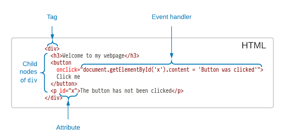
The structure of a web-page is dictated by a tree structure called the Document Object Model (DOM), which is an abstract representation of the tree structure of an XML or HTML document with support for event handling as might occur as a result of user interaction.
A fragment is a valid subtree structure that is not the entire document (Figure 5.5). So for example, an 'HTML fragment' is used to denote a snippet of HTML that could be embedded within an HTML document.
With the help of a CSS style sheet, the web browser paints this DOM to the screen in a way that can be viewed and interacted with by a user (see Figure 5.6). Through the use of JavaScript and event handlers, a webpage may manipulate its own DOM in response to events to produce interactive web-applications. The performance bottleneck in web-apps is usually the layout and painting stages of the browser rendering pipeline; the process by which the abstract DOM is converted to pixels on a screen.See this chromium documentation entry for more information on critical paths in browser rendering. https://www.chromium.org/developers/the-rendering-critical-path
Modern browsers support W3C standards for many advanced features: video playback, support for touch and ink input methods, drag and drop, animation, 3D rendering and many more. HTML also has a set of widely supported accessibility features called ARIA which can be used to ensure that apps are accessible to all. The power of web-apps to create portable, fully interactive user interfaces has clear applications for ITP some of the systems studied in Section 5.1 such as Globular and Incredible Proof Machine already make use of web technologies.
Anatomy of an HTML fragment.
Interaction loop for a typical web-app. A DOM tree is painted using a CSS file to produce a viewable webpage. User interaction invokes event handlers which manipulate the DOM, causing a repaint.

The ProofWidgets framework places an ITP system within this interaction loop by providing a metaprogramming interface to create DOM fragments and to update the DOM in response to user interaction. Here, a fragment is any potential subtree of a full document. These fragments are then sent to the client editor which mounts this fragment within an embedded web-browser for viewing. If the user interacts with the resulting view, these interactions are sent back to the server and used to compute a new DOM fragment and update the interface.
5.2.2. Functional GUI frameworks
Most meta-level programming languages for ITPs are functional programming languagesML and Scala for Isabelle, OCaml for Coq, Lean for Lean.. However GUIs are inherently mutable objects that need to react to user interaction. Fortunately, there is a long tradition of user interface frameworks for pure-functional programming. Reactive programming [BCC+13[BCC+13]Bainomugisha, Engineer; Carreton, Andoni Lombide; Cutsem, Tom van; et al.A survey on reactive programming (2013)ACM Computing Surveys (CSUR)https://doi.org/10.1145/2501654.2501666]The term 'reactive programming' generally refers to a kind of declarative programming where calculated values are automatically updated when its dependant values update. The classic example is an Excel spreadsheet, where value changes in cells propagate to dependent cells. enables the control of the inherently mutating GUI within a pure functional programming interface. The ideas of reactive programming have achieved a wide level of adoption in web-app development thanks to the popularity of tools such as the React JavaScript libraryhttps://reactjs.org and the Elm programming language [CC13[CC13]Czaplicki, Evan; Chong, StephenAsynchronous functional reactive programming for GUIs (2013)ACM SIGPLAN Conference on Programming Language Design and Implementationhttps://doi.org/10.1145/2491956.2462161].
Elm and React are UI frameworks for creating web-apps.
The programming model used by these reactive frameworks is to model a user interface as a pure view function from a data source (e.g., a shopping list is rendered to an <li> HTML fragment) to a representation of the DOM called the Virtual DOM (VDOM).
The VDOM is a tree that represents the target state of the DOM.
To modify the UI's data in response to user interactions, an update function for converting user input events to a new version of the data is defined. For example, an update function for a shopping list defines how the list should be updated in response to recieving an 'action' such as deleting and adding a new item. Once the update function is applied and the data has been updated, the system reevaluates the view function on the new data to create a new VDOM. The browser's real DOM is then mutated to match this updated VDOM tree. This may sound inefficient - recomputing the entire VDOM tree each time - but there is an optimisation available: if the view function contains nested view functions, one can memoise these functions and avoid updating the parts of the VDOM that have not changed.
The VDOM is used because directly updating the browser's DOM is costly: as mentioned in Section 5.2.1, a bottleneck in performance for websites can be the repainting phase.
When the data updates, the view function creates a new VDOM tree.
This tree is then diffed with the previous VDOM tree to produce a minimal set of changes to the real DOM.
A diff between a pair of trees 𝑡₁ and 𝑡₂ is a list of tree editing operations (move, add, delete) that transforms 𝑡₁ to 𝑡₂.
General tree diffing is known to be NP-hard [Bil05[Bil05]Bille, PhilipA survey on tree edit distance and related problems (2005)Theoretical computer sciencehttps://doi.org/10.1016/j.tcs.2004.12.030], so a simplified algorithm is used.
In React, this diffing algorithm is called reconciliation.
In turn, Elm and React are inspired by ideas from Functional Reactive Programming (FRP). FRP was first invented by Elliot [EH97[EH97]Elliott, Conal; Hudak, PaulFunctional reactive animation (1997)Proceedings of the second ACM SIGPLAN international conference on Functional programminghttps://doi.org/10.1145/258948.258973]. FRP is distinguished from general reactive programming by the explicit modelling of time. FRP has found use in UI programming but also more broadly in fields such as robotics and signal processing. A modern example of a FRP framework is netwirehttp://hackage.haskell.org/package/netwire.
I have elected to use an API for creating user interfaces that is closer to the features of a functional user interface framework. I found that the full-FRP paradigm, where the programmer has to explicitly create programs with time, was too complex for the purposes of making a simple UI framework. In any case, the design requirement that the UI logic take place in the Lean VM but rendered by the client means that the modes of iteration are limited to the point where FRP offers no advantages over simpler paradigms. If not used carefully, full-FRP can also introduce 'time-leaks': a cycle of events trigger each other, causing the program to max out CPU and lock up. As is investigated in Lemma C.14, ProofWidgets use a weaker algebra than FRP which prevents time-leaks from occurring.
5.2.3. Code editors and client-server protocols
Some modern code editors such as Atom and VSCode are built using web technology. In order to support tooling features such as go-to-definition and hover information, these editors act as the client in a client/server relationship with an independently running process called a language server. As the user modifies the code in the client editor, the client communicates with the server: notifying it when the document changes and sending requests for specific information based on the user's interactions. In ITP this communication is more elaborate than in a normal programming language, because the process of proving is inherently interactive: the user is constantly observing the goal state of the prover and using this information to inform their next command in the construction of a proof.
The most important thing to note here is that changing the communication protocol between the client and the server is generally hard, because the developer has to update the protocol in both the server and the client. There may even be multiple clients. This makes it difficult to quickly iterate on new user interface designs. A way of solving this protocol problem is to offer a much tighter integration by combining the codebases for the editor and the ITP. This is the approach taken by Isabelle/PIDE/jEdit [Wen12[Wen12]Wenzel, MakariusIsabelle/jEdit-A Prover IDE within the PIDE Framework. (2012)Intelligent Computer Mathematics - 11th International Conferencehttps://doi.org/10.1007/978-3-642-31374-5_38] and has its own trade-offs as discussed in Section 5.1.
5.3. Research goals
In terms of the broader research questions for the thesis given in Section 1.2, this chapter is mainly concerned with enabling Question 3: presenting human-like reasoning interactively.
Specifically, ProofWidgets enables the interactive presentation of the Box calculus developed in Chapter 3.
The application of ProofWidgets to HumanProof is covered in Section 5.8.
5.3.1. Architecture design goals
APIs between ITP systems and code editors such as Emacs or VSCode are large and difficult to extend and port. The ProofWidgets protocol addresses this problem by allowing an ITP user to develop new interfaces for users to interact with provers without having to learn specialised knowledge of a particular editor or technology other than basic HTML and CSSHypertext Markup Language and Cascading Style Sheets. These are the languages that control the content and styling of webpages..
Modern ITP systems such as Isabelle, Coq and Lean use advanced language servers and protocols to interface with text editors to produce a feature-rich proving experience. These systems feature standard helpers such as syntax highlighting and type hover information as would be found in normal programming language tooling. They additionally include prover-specific features such as displaying the goal state and providing interactive suggestions of tactics to apply. ITP offers some additional UI challenges above what one might find in developing an editor extension for a standard programming language, because the process of proving is inherently interactive: the user is constantly observing the goal state of the prover and using this information to inform their next command.
The original motivation for ProofWidgets was to create a specific user interface for Box.
However, while developing I became frustrated with the development workflow for prototyping the user interface in Lean: each time the interface changed, I would need to coordinate changes across three different codebases; the Lean core, the VSCode editor extension and the repository for Box.
It became clear that any approach to creating user interfaces in which the editor code needed to be aware of the datatypes used within the ITP metalogic was doomed to require many coordinated changes across multiple codebases.
This inspired my alternative approach; write a full-fledged GUIGraphical User Interface, pronounced 'gooey'. framework in the metalogic of the ITP itself.
This approach has the advantage of tightening the development loop and has more general use outside of my particular project (as I will show in Section 5.7.4).
As Bertot and Théry [BT98[BT98]Bertot, Yves; Théry, LaurentA generic approach to building user interfaces for theorem provers (1998)Journal of Symbolic Computationhttps://doi.org/10.1006/jsco.1997.0171] note, there are two approaches available to create a reusable user interface for a theorem prover:
A deep integration between a code editor and a specific prover. This is the approach taken by Isabelle/PIDE/jEdit [Wen12[Wen12]Wenzel, MakariusIsabelle/jEdit-A Prover IDE within the PIDE Framework. (2012)Intelligent Computer Mathematics - 11th International Conferencehttps://doi.org/10.1007/978-3-642-31374-5_38], although more recently VSCode support has become available [Wen18[Wen18]Wenzel, MakariusIsabelle/PIDE after 10 years of development (2018)UITP workshop: User Interfaces for Theorem Provers. https://sketis.net/wp-content/uploads/2018/08/isabellepide-uitp2018.pdf §3]. I call this the monolithic approach.
Stipulate a protocol between client editors and provers. Here we can either have many clients to one prover (e.g., the Lean 3 server protocol is supported by both Emacs and VSCode extensions); or one client to many provers, as Proof General [Asp00[Asp00]Aspinall, DavidProof General: A generic tool for proof development (2000)International Conference on Tools and Algorithms for the Construction and Analysis of Systemshttps://link.springer.com/content/pdf/10.1007/3-540-46419-0_3.pdf] achieved. I call this the protocol approach.
Focussing on the second approach, the protocol used is typically high level. That is, the protocol is stated in terms of concepts in the prover; for example, the SerAPI protocol [Gal16[Gal16]Gallego Arias, Emilio JesúsSerAPI: Machine-Friendly, Data-Centric Serialization for Coq (2016)Technical Reporthttps://hal-mines-paristech.archives-ouvertes.fr/hal-01384408/file/serapi.pdf] used by Coq provides a high level of granularity for extracting goal states and inspecting Coq expressions and proof objects. While such an API enables fine control over the prover through an external tool such as an editor, the API is large and any changes to the API or additional features require changes in multiple places and potentially introduce incompatibilities.
I argue here that having a wide protocol such as this is detrimental to the agility of prover development. In contrast, the ProofWidgets framework provides a "prover ↔ editor" protocol that removes the need for an editor to be aware of the internal representations of the prover. This protocol works by reworking the "client ↔ server" API to instead support the rendering of arbitrary interactive user interfaces. In the ProofWidgets protocol, the code responsible for the layout and event handling of these interfaces is moved to the core ITP, instead of being the responsibility of the editor. This has the effect of creating a full, general purpose GUI framework within a theorem prover.
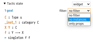
Here is a concrete example to motivate this design choice: in the development of the Lean VSCode extension, it was requested that it should be possible to filter some of the variables in the goal state to declutter the output window (see Figure 5.7). The Lean community originally achieved this by reparsing the textual goal state emitted by the Lean server component and removing the filtered items using regular expressions. This worked, but it required adding some specific code for the VSCode client -- supporting this feature in other editors would require rewriting this filtering code. Additionally, if the Lean server changes how the goal state is formatted, this filtering code would need to be rewritten. Even if an API which allows more semantic access to the expression structure is used such as SerAPI [Gal16[Gal16]Gallego Arias, Emilio JesúsSerAPI: Machine-Friendly, Data-Centric Serialization for Coq (2016)Technical Reporthttps://hal-mines-paristech.archives-ouvertes.fr/hal-01384408/file/serapi.pdf], we still have the problem that the filtering code has to be written multiple times for each supported editor. Using ProofWidgets, this filtering code can be written once in Lean itself and it works in any editor that supports the ProofWidgets API (at the time of writing VSCode and a prototype version of the web editor). Furthermore, Lean users are free to make any custom tweaks to the UI without needing to make any changes to editor code.
Demonstration of hypothesis filtering in Lean. Selecting the items from the dropdown menu with show or hide the hypotheses of the goal state according to their type. The original version of this feature was implemented in JavaScript as part of the VSCode Lean. Now the same thing is implemented within Lean as a ProofWidget. The effect of this choice is that the menu is now implemented entirely within Lean and without needing to update the VSCode extension.
Another motivation for ProofWidgets was to add 'structural pretty printing' or 'proof-by-pointing' as Théry and Bertot call it [BT98[BT98]Bertot, Yves; Théry, LaurentA generic approach to building user interfaces for theorem provers (1998)Journal of Symbolic Computationhttps://doi.org/10.1006/jsco.1997.0171]. This is where pretty-printed strings have information attached to them that provides detail on the structure of the original expression that produced the string. In other frameworks that implement proof-by-pointing such as KeY [ABB+16[ABB+16]Ahrendt, Wolfgang; Beckert, Bernhard; Bubel, Richard; et al.Deductive Software Verification - The KeY Book (2016)publisher Springerhttps://doi.org/10.1007/978-3-319-49812-6] and later versions of Proof General [Asp00[Asp00]Aspinall, DavidProof General: A generic tool for proof development (2000)International Conference on Tools and Algorithms for the Construction and Analysis of Systemshttps://link.springer.com/content/pdf/10.1007/3-540-46419-0_3.pdf], a tight integration between the code editor used by the ITP and the pretty-printing system is required. As is shown in Section 5.5, the design of ProofWidgets means that all of the code for creating and interacting with these complex structures can be handled within the ITP system's metalogic.
The three enabling technologies of the ProofWidgets framework are:
the introduction of web-based code editors such as Atom and Microsoft Visual Studio Code (VSCode);
metaprogramming frameworks for creating programs that manipulate and inspect expressions and tactic states from within theorem provers. The primary example here is the Lean metaprogramming framework [EUR+17[EUR+17]Ebner, Gabriel; Ullrich, Sebastian; Roesch, Jared; et al.A metaprogramming framework for formal verification (2017)Proceedings of the ACM on Programming Languageshttps://doi.org/10.1145/3110278]. However other metaprogramming systems such as those found in Isabelle are also available.
modern, functional, reactive user interface frameworks for the web such as Elm and React.
5.3.2. Design goals
The ProofWidgets framework has the following design goals. The principle behind these goals is ease-of-use for people creating their own ProofWidgets, as well as ensuring that as much code as possible is present in Lean itself.
Programmers write GUIs using the metaprogramming framework of the ITP.
Programmers are given an API that can produce arbitrary DOM fragments, including inline CSS styles.
No cross-compilation to JavaScript or WebAssembly: the GUI-generating code must run in the same environment as the tactic system. This ensures that the user interaction handlers have full access to the tactic execution context, including the full database of definitions and lemmas, as well as all of the metaprogramming library. In a cross-compilation based approach (implementation difficulty notwithstanding), the UI programmer would have to choose which parts of this context to export to the client.
To support interactively discoverable tactics, the system needs to be able to command the client text editor to modify its sourcetext. I'll expand on this point in Section 5.3.3.
The pretty printer must be extended to allow for 'interactive expressions': expressions whose tree structure may be explored interactively. I'll expand on this point in Section 5.3.4.
Programmers should be able to create visualisations of their data and proofs.
It should be convenient for programmers to be able to style their GUIs in a consistent manner.
The GUI programming model should include some way of managing local UI state, for example, whether or not a tooltip is open.
The GUI should be presented in the same output panel that the plaintext goal state was presented in. This ensures that the new features are discoverable and do not change the workflow of existing users.
The framework should be backwards compatible with the plaintext goal state system. Users should be able to opt out of the GUI if they do not like it or want to use a non web-app editor such as Emacs.
While all of these could be implemented by suitably extending the Lean server and client, this would cause the size of the API to balloon significantly as discussed in Section 5.3.1. These features require the context of Lean's goal state and tactics engine. To produce a UI would need this context to be propagated from the server to the client. The server/client API would become wide. Any new idea for improving the interface would require inventing a new part of the server/client API and an implementation spanning many different languages: Lean, C++, JavaScript, and possibly other dependants such as the web-editor and the Python API. Further, the implementation would have to occur in the Lean 3 core codebase, not an external library.
Instead, the goal of the ProofWidgets system is to sidestep this by giving the ITP system's metaprogramming framework full control over the UI of the goal state. By choosing this lower level of abstraction, the time required to create new and experimental interactive features is drastically reduced, because ProofWidgets can be developed in real time by just editing the code in a single code file within the prover's project. This has already proved useful several times in the Lean implementation of this protocol, for example, a go-to-definition button for expressions in the type information viewer was added by just changing a few lines of code in the mathlib codebase.
5.3.3. Discoverable tactics
Often a beginner to ITP is confronted with a goal state where they don't know which tactic could be used to progress in the proof. A key tenet of making a user interface intuitive to use is to make available actions discoverable (also called learnability within the HCI literature [GFA09]). As shown in Figure 5.8, ProofWidgets allow one to make a goal state which actively suggests available tactics to the user.
Example of a suggested tactic widget for a goal. Clicking the apply H₁ button will insert apply H₁ into the proof document and advance the tactic state.

5.3.4. Interactive term rewriting
Currently in Lean, if one wants to solve an equality problem such as (x + 3) * (x + 1) = x * x + 4 * x + 3 without resorting to a specialised tactic such as ring or a full-blown solver, you have the option of using a general equational rewriting tactic rewrite or simp.
The tactic rewrite h where h : Π ..𝑥𝑠, 𝑙𝑠 = 𝑟𝑠 finds a subterm of the goal which the 𝑙𝑠Left Hand Side of h matches with and replaces it with the 𝑟𝑠 with appropriate substitutions of the variables 𝑥𝑠. Similarly, simp repeatedly performs rewrites of the goal from a curated set of lemmas.
These tactics do not give an easy way to explore subterms of an expression to interactively find where to apply rewrites.
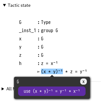
With ProofWidgets, one can build a tool where one can click directly on a subterm of a goal state and see the available rewrites at that point, or to see what an expression will look like after applying simp.
An example of this is shown in Figure 5.9.
A widget goal view with subterm-sensitive suggestions of rewriting lemmas.
Clicking on the subterm (x * y)⁻¹ suggests the rewrite rule shown in purple.
Since the widgets system is also able to influence the code editor, it is also possible to build user interfaces that interactively build the proof script in the Lean document.
5.3.5. Non-goals
In order to scope the design of the system, I specify some features that are not a requirement for the design of ProofWidgets.
No animation and time-continuous interactions: I don't address the task of creating a framework that is capable of complex reactive animation or continuous, mouse and touch driven interactions like pinching and dragging. Although many existing FRPFunctional Reactive Programming, see Section 5.2.2 for more details. frameworks are built for these, it seems unlikely that Lean 3's VMVirtual Machine. Lean 3 compiles to bytecode which is run in its VM. is going to be efficient enough to support them. This does not mean that no animations are possible in ProofWidgets, however. Complex animations are possible through CSS transitions without needing to involve a programmatic event at all.
No concurrency and asynchronous tasks: By this I mean the ability for the Lean server to 'push' events to the client after some long-running task has completed. This is not a requirement mainly in the name of keeping the implementation simple enough for a first proof-of-concept version. In Section 5.9 I offer some thoughts on how this could be implemented.
No compilation to javascript: This may become\ possible in Lean 4 with the help of Lean 4's compiler and WebAssembly, but for now the UI logic of ProofWidgets should run entirely on the (local) Lean server. This has a number of advantages: it is much less complex than a cross-compilation approach and it allows for the entirety of Lean's proof state and prover apparatus to be available.
Don't support all user interface modalities: Modern browser user interfaces offer many different methods of interaction; drag and drop, touch gestures such as pinch to zoom. For now, the ProofWidgets framework only offers a small subset of these, namely mouse events and text input. However HTML ARIA attributes are supported by ProofWidgets so that they can be made accessible to differently-abled people.
Performance should be 'good enough': As mentioned in Section 5.2.1, the performance bottleneck for web apps is typically the layout and painting stages of the browser rendering pipeline. Using a client-side framework such as ReactJS to minimise the number of changes to the browser's DOM gives acceptable performance for most use cases. In Section 5.9 I also provide some ideas on how to improve the performance of ProofWidgets.
5.4. System description
The design goals discussed in Chapter 1 led me to design ProofWidgets to use a declarative VDOM-based architecture (see Section 5.2.2) similar to that used in the Elm programming language [CC13[CC13]Czaplicki, Evan; Chong, StephenAsynchronous functional reactive programming for GUIs (2013)ACM SIGPLAN Conference on Programming Language Design and Implementationhttps://doi.org/10.1145/2491956.2462161] and the React JavaScript library as discussed in Section 5.2.2. By using the same programming model, I can leverage the familiarity of potential users with commonly used React and Elm APIs. In the following sections I detail the design of ProofWidgets, starting with the UI programming model Section 5.4.1 and the client/server protocol Section 5.4.2.
5.4.1. UI programming model
This section is about the API that users of the ITP system can use to implement user interfaces created with the protocol given in Section 5.4.2.
Most meta-level programming languages for ITPs are functional programming languagesML and Scala for Isabelle, OCaml for Coq, Lean for Lean. So the mutable DOM paradigm shown in Section 5.2.1 is going to not be suitable for our purposes because functional programming languages act predominantly on immutable datastructures. Fortunately, as discussed in Section 5.2.2, there are a number of functional paradigms available for building user interfaces in an immutable way. I summarise their operation here and a more detailed overview of the API is given in Appendix C. The design of the UI building API is inspired by the design used in the Elm programming language [CC13[CC13]Czaplicki, Evan; Chong, StephenAsynchronous functional reactive programming for GUIs (2013)ACM SIGPLAN Conference on Programming Language Design and Implementationhttps://doi.org/10.1145/2491956.2462161].
New user interfaces are created using the Html and Component types.
A user may define an HTML fragment by constructing a member of the inductive datatype Html, which is either an element (e.g., <div></div>), a string or a Component object to be discussed shortly.
These fragments can have event handlers attached to them.
For example, in (5.10), a button is created by defining a handler ℎ : Unit → α sending the unit type to a member of some type α.
When this interface is rendered in the client and the button is clicked, the server is notified and causes the node to emit the element ℎ() : α.
In (5.10), when the button is pressed it will emit 4 : ℕ.
The value of ℎ() is then propagated towards the root of the Html tree until it reaches a component.
Simple example of an event handler. The function button takes an event handler ℎ and some text for the button content.
The value the handler returns will be emitted in the event of a button click.
button : (ℎ : Unit → α) → String → Html αexampleButton : Html ℕ := button (() ↦ 4) "click me"
Now we need to provide a mechanism for doing something with this emitted object.
A component is an inductive datatype taking two type parameters: π (the props type) and α (the action type)This is designed to be familiar to those who use React components: https://reactjs.org/docs/components-and-props.html..
It represents a stateful object in the user interface tree where the state s : σ can change as a result of a user interaction event.
By 'stateful' we mean an object which holds some mutating state for the lifetime of the user interface.
Through the use of components, it is possible to describe the behaviour of this state without having to leave the immutable world of a pure functional programming language.
Three functions determine the behaviour of a component:
init : π → σinitialises the state.view : π → σ → Html αmaps the state to a VDOM tree.update : π → α → σ → σ × Option βis run when a user event is triggered in the child HTML tree returned byview. The emitted value𝑎 : αis used to produce a tupleσ × Option βconsisting of a new state𝑠 : σand optionally, a new event𝑏 : βto emit. If the new event is provided, it will propagate further towards the root of the VDOM tree and be handled by the next component in the sequence.
A simple example of a counter component is shown in (5.11) and Figure 5.12.
In (5.11), the component has an integer s : ℤ for a state, and updating the state is done through clicking on the 'increment' and 'decrement' buttons which will emit 1 and -1 when clicked. The values a are used to update the state to a + s. Creating stateful components in this way has a variety of practical uses when building user interfaces for inspecting and manipulating the goal state. We will see in Section 5.5 that a state is used to represent which expression the user has clicked.
Indeed, an entire tactic state can be stored as the state of the component.
Then the update function runs various tactics to update the tactic state and output the new result.
Code for a simple counter app showcasing statefulness. The output is shown in Figure 5.12
⟨ σ := ℤ, s₀ := 0, view := s ↦<div>button (() ↦ 1) "increment"<span>{to_string s}</span>button (() ↦ -1) "decrement"</div>, update := (a : ℤ) ↦ (s : ℤ) ↦ a + s⟩
The resulting view of a simple counter component.
5.4.2. The server protocol
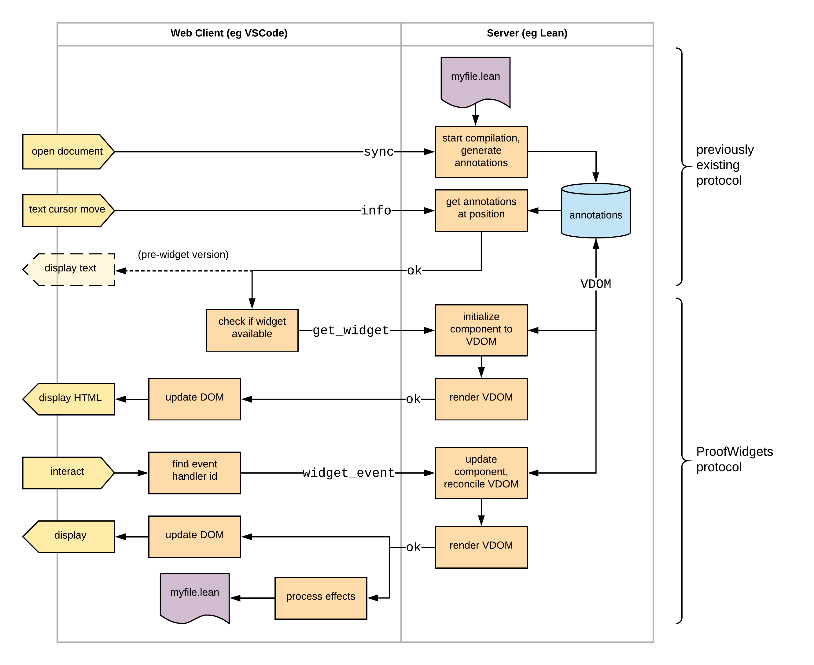
The communication protocol between the client editor and the ITP server is illustrated in Figure 5.13. A more detailed overview on the specifics for the Lean implementation can be found in the leanprover-community documentation.
The architecture of the ProofWidgets client/server communication protocol. My contribution is present in the section marked 'ProofWidgets protocol'. Arrows that span the dividing lines between the client and server components are API requests and responses. The arrows crossing the boundary between the client and server applications are sent in the form of JSON messages. Rightward arrows are requests and leftward arrows are responses.
Once the programmer has built an interface using the API introduced in Section 5.4.1, it needs to be rendered and delivered to the browser output window.
ProofWidgets extends the architecture discussed in Section 5.2.3 with an additional protocol for controlling the life-cycle of a user interface rendered in the client editor.
When a sourcefile for the prover is opened (in Figure 5.13, myfile.lean), the server begins parsing, elaborating and verifying this sourcefile as usual.
The server incrementally annotates the sourcetext as it is processed and these annotations are stored in memory.
The annotations include tracing diagnostics messages as well as thunksA thunk is a lazily evaluated expression. of the goal states at various points in a proof.
When the user clicks on a particular piece of sourcecode in the editor ('text cursor move' in Figure 5.13), the client makes an info request for this position to the server, which responds with an ok response containing the logs at that point.
The ProofWidgets protocol extends the info messages to allow the prover to similarly annotate various points in the document with VDOM trees (see Section 5.2.2) created from components.
These annotating components (see Section 5.4.1) have the type Component TacticState Empty where TacticState is the current state of the prover and Empty is the uninhabited type.
A default component for rendering goals of proof scripts is provided, but users may override this with their own components.
The VDOM trees are derived from this component, where the VDOM has the same tree structure as the Html datatype (i.e., a tree of elements, strings and components), but the components in the VDOM tree also contain the current state and the current child subtree of the component. This serves the purpose of storing a model of the current state of the user interface.
These VDOMs can be rendered to HTML fragments that are sent to the client editor and presented in the editor's output window.
There are two ways to create a VDOM tree from a component: from scratch using initialisation or by updating an existing VDOM tree using reconciliation.
Initialisation is used to create a fresh VDOM tree.
To initialise a component, the system first calls init to produce a new state 𝑠.
𝑠 is fed to the view method to create an Html tree 𝑡.
Any child components in 𝑡 are recursively initialised.
The inputs to reconciliation are an existing VDOM tree 𝑣 and a new Html tree 𝑡. 𝑡 is created when the view function is called on a parent component.
The goal of reconciliation is to create a new VDOM tree matching the structure of 𝑡, but with the component states from 𝑣 transferred over.
The tree diffing algorithm that determines whether a state should be transferred is similar to the React reconciliation algorithm and so I will omit a discussion of the details here.
The main point is that when a user interface changes, the states of the components are preserved to give the illusion of a mutating user interface.
For interaction, the HTML fragment returned from the server may also contain event handlers.
Rather than being calls to JavaScript methods as in a normal web-app, the client editor intercepts these events and forwards them to the server using a widget_event request. The server then updates the component according to the event to produce a new Html tree that is reconciled with the current VDOM tree.
The ProofWidgets framework then responds with the new HTML fragment derived from the new VDOM tree.
In order to ensure that the correct event handler is fired, the client receives a unique identifier for each handler that is present on the VDOM and returns this identifier upon receiving a user interaction.
So, in effect, the ITP server performs the role of an event handler: processing a user interaction and then updating the view rendered to the screen accordingly.
In addition to updating the view, the response to a widget_event request may also contain effects.
These are commands to the editor, for example revealing a certain position in the file or inserting text at the cursor position.
Effects are used to implement features such as go-to definition and modifying the contents of sourcefiles in light of a suggested modification to advance the proof state.
If a second user interaction event occurs while the first is being handled, the server will queue these events.
The architecture design presented above is a different approach to how existing tools handle the user interface. It offers a much smaller programming API consisting of Component and Html and a client/server protocol that supports the operation of arbitrary user interfaces controlled by the ITP server. Existing tools (Section 5.1) instead give fixed APIs for interaction with the ITP, or support rendering of custom HTML without or with limited interactivity.
To implement ProofWidgets for an ITP system, it is necessary to implement the three subsystems that have been summarised in this section: a programming API for components; the client editor code (i.e., the VSCode extension) that receives responses from the server and inserts HTML fragments to the editors output window; and the server code to initialise, reconcile and render these components.
5.5. Interactive expressions
This section is about using ProofWidgets to perform 'interactive pretty printing' where expressions are rendered to HTML with explicit structure information. As discussed in Section 5.1, structural pretty printing is not a novel feature, however the way in which it is designed here makes structural pretty printing extensible and accessible to the metaprogramming framework. The ability to interactively pretty print expressions is a critical part of implementing the design goal of interactive term rewriting discussed in Section 5.3.4.
An example of the system in operation is given in Figure 5.14: as one hovers over the various expressions and subexpressions in the infoview, one gets semantically correct highlighting for the expressions, and when you click on a subexpression, a tooltip appears containing type information. This tooltip is itself a widget and so can also be interacted with, including opening a nested tooltip.
Screenshot showing the interactive expression view in action within the Lean theorem prover. The left-hand pane is the Lean source document and the right-hand pane is the infoview showing the context and expected type at the editor's cursor. There are two black tooltips giving information about an expression in the infoview.
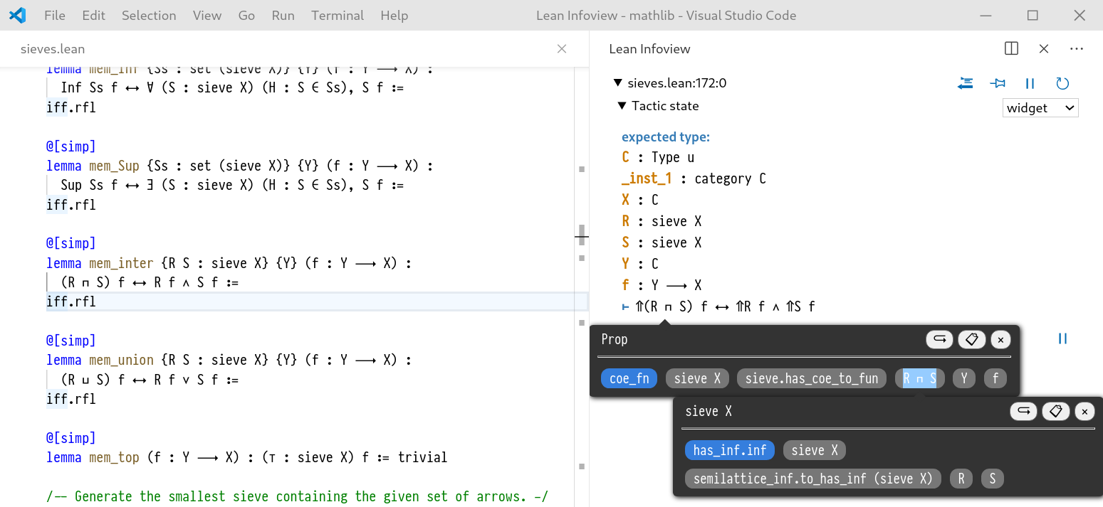
A number of other features are demonstrated in Figure 5.14:
Hovering over subterms highlights the appropriate parts of the pretty printed string.
The buttons in the top right of the tooltip activate effects including a "go to definition" button and a "copy type to clipboard" button.
Expressions within the tooltip can also be explored in a nested tooltip. This is possible thanks to the state tracking system detailed in the previous section.
Note that the Lean editor already had features for displaying type information for the source document with the help of hover info, however this tooltip mechanism is only textual (not interactive) and only works on expressions that have been written in the source document. Prior to ProofWidgets there was no way to inspect expressions as they appeared in the infoview.
All of the code which dictates the appearance and behaviour of the infoview widget is written in Lean and reloads in real time when its code is changed. This means that users can produce their own custom tooltips and improve upon the infoview experience without needing to leave the project.
5.5.1. Tagged strings
Before ProofWidgets, the Lean pretty-printer would take an expression and a context for the expression and produce an member of the format type.
This is implemented as a symbolic expression (shortened to 'sexpr') a la LISP [McC60[McC60]McCarthy, JohnRecursive functions of symbolic expressions and their computation by machine, Part I (1960)Communications of the ACMhttps://doi.org/10.1145/367177.367199].
For ProofWidgets, I modified Lean's C++ pretty printer so that it would also tag certain sexprs with two pieces of data: the subexpression that produced the substring and an expression address indicating where the subexpression lies in the parent expression. The expression address is a list of expression coordinates used to reference subterms of an expression. An expression coordinate is a number that indexes the recursive arguments in the constructors for an expression. In this sense it is doing the same job as the coordinates defined in Section 2.3.2. That is, is parametrises the lenses that are available for subexpressions. A simplified example of the pseudocode is shown in (5.15).
Pseudocode for implementing tagged strings from expressions.
The TaggedString datastructure expands on a Wadler-style formatting tree by including 'tagged' portions of the expression. A tag includes the subexpression that the string represents and an Address object allowing one to determine which subtree of the parent expression is being represented.
Expr ::=| var : String → Expr| app : Expr → Expr → Expr| lam : String → Expr → Expr| const : String → ExprCoord ::=| f | a | lam_bodyAddress := List Coordget : Address → Expr → Option Expr| [] ↦ 𝑒 ↦ some 𝑒| [f, ..𝑡] ↦ app 𝑙 𝑟 ↦ get 𝑡 𝑙| [a, ..𝑡] ↦ app 𝑙 𝑟 ↦ get 𝑡 𝑟| [lam_body, ..𝑡] ↦ lam 𝑠 𝑏 ↦ get 𝑡 𝑏| _ ↦ _ ↦ noneset : Address → Expr → Expr → Expr := ...coords : Expr → List Address := ...TaggedString ::=| tag : (Expr × Address) → TaggedString → TaggedString| append : TaggedString → TaggedString → TaggedString| of_string : String → TaggedStringpretty_print : Expr → Tactic TaggedString
In this way, the TaggedString acts as a reversed source-mapIn the context of compilers, a source-map is a file that identifies parts of the compiler-output with the source code. This enables the use of diagnostic tools such as debuggers. between the resulting sexpr and the original expression, even when using specialised syntax such as lists [1,2,3] and set comprehensions.
This tagged string is used to create widgets that allow users to interactively inspect various parts of the expression in the infoview.
In the case of a subexpression being below a binder (e.g., in the body of a lambda expression) the pretty printer instantiates the de-Bruijn variable with a dummy local variable, so the given subexpression doesn't contain free de-Bruijn variables and still typechecks without having to know the binders above the subexpression.
Below are some diagrams to illustrate the relationship between a TaggedString and an Expr.
An expression tree for (x ++ y) ++ [1,2]. Each f or a above the lines is an expression coordinate.
The red [a,a,f,a] example of an expression address, corresponding to the red line on the tree.
Each green circle in the tree will pretty-print to a string independent of the expression tree above it.
While the pretty-printed expression involves infix operators, these expression trees are stored internally as function application trees.
The pretty-printer is responsible for determining whether these trees should be printed in infix form or not.

The TaggedString tree produced by pretty-printing the expresssion (x ++ y) ++ [1,2].
The green circles are TaggedString.tag constructors and the blue address text within is the relative address of the tag in relation to the tag above it.
So that means that the full expression address for a subterm can be recovered by concatenating the Addresses above it in the tree. E.g., the 2 subexpression is at [] ++ [a] ++ [a,f,a] = [a,a,f,a]

There are two versions of the code for interactive expression rendering: the original core Lean version and the more experimental mathlib version.
To render an interactive expression given a TaggedString, define a stateful Component (TacticState × Expr) Empty. The TacticState object includes the metavariable context and a local context in which the given expression is valid.
The state of the component includes an optional Address of the subexpression.
When the user hovers over a particular point in the printed TaggedString, the expression address corresponding to that part of the string is calculated using the tags and this address is set as the state of the component.
This address is then used to colour in the portion of the string that is currently hovered over by the user's mouse cursor which gives the semantic-aware highlighting effect.
When the user clicks on a subexpression, a tooltip appears containing type information as well as some details on it such as the type and the available explicit arguments. Users can create their own tooltips using attr.popper.
The stateful component framework developed in the last section means that these expressions can themselves be interactive expressions and we can recursively expand the selection, as shown in Figure 5.14 earlier.
5.6. Related work
In Section 5.1 I covered other graphical user interfaces for proof assistants. Here I will relate them to ProofWidgets. As discussed in Section 5.3.1, the main differentiating feature of ProofWidgets is its use of web technology for rendering and allowing the metaprogramming language of the thoerem prover to take full responsibility for constructing the DOM of the GUI and handling user interactions. This contrasts with the two other approaches to constructing GUIs for theorem provers; which I dubbed the monolithic approach and protocol approach in Section 5.3.1.
The first related architecture is Isabelle's Prover IDE (PIDE). An advantage of the ProofWidgets approach compared to PIDE's is that the API between the editor and the prover can be smaller since, in ProofWidgets, the appearance and behaviour is entirely dictated by the server. In contrast, the implementation of PIDE is tightly coupled to the bundled jEdit editor, which has some advantages over ProofWidgets in that it gives more control to the developer to create new GUIs. The downside of PIDE's approach here is that one must maintain this editor and so supporting any other editor with feature-parity becomes difficult. ProofWidgets also makes use of modern web technology which is ubiquitously supported. In contrast, PIDE uses a Java GUI library called Swing. Creating custom UIs in PIDE requires coding in both Scala and StandardML. The result does not easily generalise to the VSCode Isabelle extension because VSCode is based on web-technology instead of the Swing framework, so if the custom UI is to also support the VSCode extension, some JavaScript must also be written.
The example of the protocol approach that I will elect to compare ProofWidgets with is the SerAPI protocol for Coq. SerAPI is a library for machine-machine interaction with the Coq theorem prover. SerAPI contrasts to ProofWidgets in that it expects another program to be responsible for displaying graphical elements such as goal states and visualisations; in the ProofWidgets architecture all of the UI appearance and behaviour code is also written in Lean, and the web-app client can render general GUIs emitted by the system.
Theorema [BJK+16[BJK+16]Buchberger, Bruno; Jebelean, Tudor; Kutsia, Temur; et al.Theorema 2.0: computer-assisted natural-style mathematics (2016)Journal of Formalized Reasoninghttps://doi.org/10.6092/issn.1972-5787/4568] is a tool integrated into Wolfram Mathematica, a proprietary computer algebra system. Mathematica comes with its own widget system, which can also be used in a web setting, and so by allowing Mathematica do the heavy-lifting, Theorema is able to have fine-grained control over its GUI whilst remaining portable. However, this approach means that it is tied to the proprietary Mathematica ecosystem, whereas ProofWidgets only depends on web standards which are open.
As discussed in Section 5.1, there is a cohort of now extinct theorem provers that had a great deal of focus on graphical, multimodal representations of data; LΩUI for Ωmega [BCF+97[BCF+97]Benzmüller, Christoph; Cheikhrouhou, Lassaad; Fehrer, Detlef; et al.Ωmega: Towards a mathematical assistant (1997)Automated Deduction - CADE-14https://doi.org/10.1007/3-540-63104-6_23, SHB+99[SHB+99]Siekmann, Jörg; Hess, Stephan; Benzmüller, Christoph; et al.LOUI: Lovely OMEGA user interface (1999)Formal Aspects of Computinghttps://doi.org/10.1007/s001650050053], HyperProof [BE92[BE92]Barwise, Jon; Etchemendy, JohnHyperproof: Logical reasoning with diagrams (1992)Working Notes of the AAAI Spring Symposium on Reasoning with Diagrammatic Representationshttps://www.aaai.org/Papers/Symposia/Spring/1992/SS-92-02/SS92-02-016.pdf] and XBarnacle [LD97[LD97]Lowe, Helen; Duncan, DavidXBarnacle: Making Theorem Provers More Accessible (1997)14th International Conference on Automated Deductionhttps://doi.org/10.1007/3-540-63104-6_39] for the CLAM prover. I hope that ProofWidgets can enable a rekindling of research into these more inventive and visual representations of proof states.
5.7. Implementation of Widgets in Lean
This section explains the underlying model for how ProofWidgets are created and mutated as the user interacts with them.
As discussed in Section 5.4.2 Lean has a server mode in which Lean works with a code editor such as VSCode or Emacs to provide an interactive editing environment. In server mode, Lean monitors open sourcefiles in the open project and maintains a structure called the log tree which attaches information providers to locations in the sourcefiles. For instance, the log tree holds the goal state of an interactive-mode proof and logging information which is revealed to the user when they navigate their cursor to that position.
Thanks to Lean's extensive meta-programming features [EUR+17[EUR+17]Ebner, Gabriel; Ullrich, Sebastian; Roesch, Jared; et al.A metaprogramming framework for formal verification (2017)Proceedings of the ACM on Programming Languageshttps://doi.org/10.1145/3110278], the Lean programmer can attach their own messages with the tactic.save_info_thunk : thunk format → tactic unit function.
save_info_thunk attaches a thunk to the log tree containing a procedure to generate a logging message.
When the user clicks over that particular part of the document in the client, the Lean server evaluates the thunk and produce a formatted piece of text to display to the user in the infoview.
This process is shown in the dashed part of Figure 5.13.
The ProofWidgets framework adds an additional kind of object to the log tree using tactic.save_widget : (tactic_state ⇨ empty) → tactic unit with a component as its argument.
As discussed in Section 5.4.1, the log tree entry that is created through save_widget attaches some state to the object which does mutate.
In this way, it is possible to model ephemeral UI state such as whether the user has opened a tooltip.
The implementation code can be found in the widget.cpp file in the leanprover-community/lean GitHub repository.
5.7.1. Reconciliation of HTML
Informally, the purpose of the reconciliation step is to compare an old tree and a new tree and try to find a way of matching up the new tree to the old tree.
This is required to make sure that the internal states of sub-components in the tree are preserved even if the ordering of the components is changed.
For example, suppose we had a list of counter subcomponents each with an integer state.
Then if we reorder these components in the list we should expect that these counter states are not lost or scrambled.
The general version of this problem is a tree-editing problem, which is known to be NP-hard [Bil05[Bil05]Bille, PhilipA survey on tree edit distance and related problems (2005)Theoretical computer sciencehttps://doi.org/10.1016/j.tcs.2004.12.030], however as noted by ReactJS, we can get acceptable performance with heuristics and by allowing the created UI to add an identifying attribute called a key to elements.
In the Lean implementation, if the system is reconciling a list of child attributes, it will reconcile pairs of elements from the old and the new tree that share a key. Behaviour in the unrecommended case of more than a pair having the same key is handled by pairing off the first in the list. Any remaining pairs of elements are reconciled in the order they appear in the list.
5.7.2. CSS
The Lean ProofWidgets system per se only emits JSON that is converted to HTML. But for the web-client and viewer implementations it also necessary to include a style sheet to make it look visually appealing. Rather than providing a mechanism for including stylesheets, the implementations load a stylesheet library called Tachyons.
Tachyons is a 'functional CSS' library, which means that CSS classes each perform one very precise job.
So for example, if you want to render a purple button with rounded corners and padding you would include the attribute className "link pa2 br2 white bg-purple".
Tachyons then has some small CSS class selectors (e.g., .pa2 { padding: .5rem; }) that style the DOM element appropriately.
These CSS classes have a couple of benefits over inline styles: they are terser and they enforce a set of standardised colours and spacing that make it easier to provide a more consistent appearance.
By using this approach to styling one can remove the need for a specially tailored stylesheet, which is perfect for the use case of ProofWidgets.
One drawback of rendering expressions in HTML is that the CSS typesetting paradigm is very different to the Wadler-style linebreaking algorithm [Wad03[Wad03]Wadler, PhilipA prettier printer (2003)The Fun of Programming, Cornerstones of Computinghttp://www.cs.ox.ac.uk/publications/books/fop] that Lean's normal pretty printer uses. Daniel Fabian discovered a CSS trick to automatically linebreak expressions properly if the content box is too narrow.
5.7.3. Supported Effects
There is an additional hook for dealing with side-effects: changes to the client editor document state in response to widget events. Currently the supported effects are: highlighting a portion of the document; inserting text into the document; putting text into the paste buffer; opening a file (to implement go-to-definition).
This is the final piece of the puzzle to produce an interactive proof production experience: allowing ProofWidgets to affect the proof script.
In the context of the Lean implementation, ProofWidgets allows a Lean programmer to embed an interactive GUI at any point in the Lean document. Thanks to Lean's extensive metaprogramming features [EUR+17[EUR+17]Ebner, Gabriel; Ullrich, Sebastian; Roesch, Jared; et al.A metaprogramming framework for formal verification (2017)Proceedings of the ACM on Programming Languageshttps://doi.org/10.1145/3110278], the user can write their GUI code in Lean itself. Widgets are already being used in mathlib, the Lean mathematics library [Com20[Com20]The Mathlib CommunityThe Lean Mathematical Library (2020)Proceedings of the 9th ACM SIGPLAN International Conference on Certified Programs and Proofshttps://doi.org/10.1145/3372885.3373824].
5.7.4. Community-built ProofWidgets
ProofWidgets has already found use within the wider Lean community. See Figure 5.18 for a quilt of projects that people have made using ProofWidgets. Of particular note is the Mathematica Bridge by Lewis and Wu [Lew17[Lew17]Lewis, Robert Y.An Extensible Ad Hoc Interface between Lean and Mathematica (2017)Proceedings of the Fifth Workshop on Proof eXchange for Theorem Proving, PxTP 2017, Brasília, Brazil, 23-24 September 2017https://doi.org/10.4204/EPTCS.262.4], which connects Lean to Wolfram Mathematica and uses the ProofWidgets framework to show Lean functions plotted by Mathematica.
Community-made projects using ProofWidgets, in order these are:
explode proof viewer by Minchao Wu.
Mathematica bridge by Robert Y Lewis and Minchao Wu.
Sudoku solver and visualiser by Markus Himmel.
Rubik's cube formalisation by Kendall Frey.


5.8. Visualising Boxes
In this section, I am going to discuss how ProofWidgets are used to create an interactive Box element.
Boxes were introduced in Chapter 3 and are the development calculus of the HumanProof system.
The first component, the visualisation system, follows the same visual rules as defined in (3.10).
This is used to create a visualisation of a box.
In order to correctly print bound variables, the visualisation code has a metavariable context as an input.
This is updated with new metavariables and local contexts as and 𝒢 Boxes are traversed.
This is simple to implement in ProofWidgets because all of the usual theorem proving apparati are available whilst constructing the user interface.
In contrast, implementing the same would be cumbersome to achieve with the 'wide API' approach discussed in Section 5.3.1.
To implement interactivity, the main component for rendering the Box is stateful, with the state being a Box and an undo stack of Boxes indicating the box-tactics that have been applied so far.
Interactivity is implemented by defining a precondition test for each box-tactic.
For example, the intro box-tactic (Section 3.5.3) has a precondition of the goal type being a ∀ binder.
If the precondition holds, the view function renders a button next to the selected goal indicating that a box-tactic is available for application on that goal or hypothesis.
The button's event handler (Section 5.4.1) then performs the box-tactic and produces a new Box which is emitted to be picked up by the main component and added to the undo stack.
An example of this can be seen in Figure 5.8.
The precondition system is needed because in some cases the box-tactic applications can take a long enough time that a noticeable lag will appear in the systemThe rule of thumb that I use is that any delay of more than half a second without a visual cue after clicking a button is jarring..
The contextual bookkeeping of performing box-tactics on a Box Zipper as worked out in Appendix A is needed to ensure that the box-tactic is sound.
5.9. Future work
In the future, I wish to improve Lean ProofWidgets in a number of ways. One simple way is in improving documentation, Appendix B provides a tutorial on using ProofWidgets in Lean that I hope to expand to more examples later.
In terms of performance, in order to produce responsive interfaces that use long-running tactics (e.g., searching a library or running a solver) it will be necessary to provide a mechanism for allowing concurrency.
At the moment, if a long-running operation is needed to produce output, this blocks the rendering process and the UI becomes unresponsive for the length of the operation.
Currently Lean has a task type which represents a 'promise' to the result of a long-running operation, which could be used to solve this problem.
This could be cleanly integrated with ProofWidgets by providing an additional hook with_task:
Adding concurrency to components with the help of with_task.
component.with_task(get_task : π → task τ): (Component ((option τ) × π) α) → (Component π α)
Here (5.19), get_task would return a long-running task object and the props for the inner component would transition from none to some 𝑡 upon the completion of the task.
Cancelling a task is implemented simply by causing a rerender.
There are also many features of web-browsers that would be worth implementing such as drag-and-drop, sliders and mouse position events. There is also currently no support for adding third party libraries such as the data visualisation library D3. Allowing support for including arbitrary JavaScript libraries to run on the client would allow this, but making such a system portable and robust is more challenging, because they would require JavaScript glue code in order to work correctly with the system. Another aesthetic consideration is finding a principled way of implementing a Wadler-style pretty printer [Wad03[Wad03]Wadler, PhilipA prettier printer (2003)The Fun of Programming, Cornerstones of Computinghttp://www.cs.ox.ac.uk/publications/books/fop] within CSS and HTML.
Currently, the server sends an entire DOM tree in every event loop, this could be replaced with a JSON patch file to save bandwidth.
I wish to reimplement ProofWidgets in Lean 4. Lean 4 has a bootstrapped compiler, so the reconciling code can be written in Lean 4 itself without having to modify the core codebase as was necessary for Lean 3. I hope that the pseudocode written in Appendix C will assist in this project. Lean 4 has an overhauled, extensible parser system [UM20[UM20]Ullrich, Sebastian; de Moura, LeonardoBeyond Notations: Hygienic Macro Expansion for Theorem Proving Languages (2020)Automated Reasoninghttps://doi.org/10.1007/978-3-030-51054-1_10] which should allow a JSX-like HTML syntax to be used directly within Lean documents.
Bibliography for this chapter
- [ABB+16]Ahrendt, Wolfgang; Beckert, Bernhard; Bubel, Richard; Hähnle, Reiner; Schmitt, Peter H.; Ulbrich, MattiasDeductive Software Verification - The KeY Book (2016)publisher Springerdoi 10.1007/978-3-319-49812-6isbn 978-3-319-49811-9https://doi.org/10.1007/978-3-319-49812-6
- [ALW07]Aspinall, David; Lüth, Christoph; Winterstein, DanielA framework for interactive proof (2007)Towards Mechanized Mathematical Assistantspages 161--175editors Kauers, Manuel; Kerber, Manfred; Miner, Robert; et al.publisher Springerdoi 10.1007/978-3-540-73086-6_15https://doi.org/10.1007/978-3-540-73086-6_15
- [Asp00]Aspinall, DavidProof General: A generic tool for proof development (2000)International Conference on Tools and Algorithms for the Construction and Analysis of Systemsvolume 1785pages 38--43editors Graf, Susanne; Schwartzbach, Michael I.organization Springerpublisher Springerdoi 10.1007/3-540-46419-0_3https://link.springer.com/content/pdf/10.1007/3-540-46419-0_3.pdf
- [BCC+13]Bainomugisha, Engineer; Carreton, Andoni Lombide; Cutsem, Tom van; Mostinckx, Stijn; Meuter, Wolfgang deA survey on reactive programming (2013)ACM Computing Surveys (CSUR)volume 45number 4pages 1--34editor Hankin, Chrispublisher ACM New York, NY, USAdoi 10.1145/2501654.2501666https://doi.org/10.1145/2501654.2501666
- [BCF+97]Benzmüller, Christoph; Cheikhrouhou, Lassaad; Fehrer, Detlef; Fiedler, Armin; Huang, Xiaorong; Kerber, Manfred; Kohlhase, Michael; Konrad, Karsten; Meier, Andreas; Melis, Erica; Schaarschmidt, Wolf; Siekmann, Jörg H.; Sorge, VolkerΩmega: Towards a mathematical assistant (1997)Automated Deduction - CADE-14volume 1249pages 252--255editor McCune, Williampublisher Springerdoi 10.1007/3-540-63104-6_23https://doi.org/10.1007/3-540-63104-6_23
- [BE92]Barwise, Jon; Etchemendy, JohnHyperproof: Logical reasoning with diagrams (1992)Working Notes of the AAAI Spring Symposium on Reasoning with Diagrammatic Representationshttps://www.aaai.org/Papers/Symposia/Spring/1992/SS-92-02/SS92-02-016.pdf
- [Bil05]Bille, PhilipA survey on tree edit distance and related problems (2005)Theoretical computer sciencevolume 337number 1-3pages 217--239publisher Elsevierdoi 10.1016/j.tcs.2004.12.030https://doi.org/10.1016/j.tcs.2004.12.030
- [BJK+16]Buchberger, Bruno; Jebelean, Tudor; Kutsia, Temur; Maletzky, Alexander; Windsteiger, WolfgangTheorema 2.0: computer-assisted natural-style mathematics (2016)Journal of Formalized Reasoningvolume 9number 1pages 149--185doi 10.6092/issn.1972-5787/4568https://doi.org/10.6092/issn.1972-5787/4568
- [Bre16]Breitner, JoachimVisual theorem proving with the Incredible Proof Machine (2016)International Conference on Interactive Theorem Provingpages 123--139editors Blanchette, Jasmin Christian; Merz, Stephanpublisher Springerdoi 10.1007/978-3-319-43144-4_8https://doi.org/10.1007/978-3-319-43144-4_8
- [BT98]Bertot, Yves; Théry, LaurentA generic approach to building user interfaces for theorem provers (1998)Journal of Symbolic Computationvolume 25number 2pages 161--194publisher Elsevierdoi 10.1006/jsco.1997.0171https://doi.org/10.1006/jsco.1997.0171
- [CC13]Czaplicki, Evan; Chong, StephenAsynchronous functional reactive programming for GUIs (2013)ACM SIGPLAN Conference on Programming Language Design and Implementationpages 411--422editors Boehm, Hans-Juergen; Flanagan, Cormacpublisher ACMdoi 10.1145/2491956.2462161https://doi.org/10.1145/2491956.2462161
- [Com20]The Mathlib CommunityThe Lean Mathematical Library (2020)Proceedings of the 9th ACM SIGPLAN International Conference on Certified Programs and Proofspages 367–381publisher Association for Computing Machinerydoi 10.1145/3372885.3373824isbn 9781450370974https://doi.org/10.1145/3372885.3373824
- [EH97]Elliott, Conal; Hudak, PaulFunctional reactive animation (1997)Proceedings of the second ACM SIGPLAN international conference on Functional programmingpages 263--273editors Peyton Jones, Simon L.; Tofte, Mads; Berman, A. Michaeldoi 10.1145/258948.258973https://doi.org/10.1145/258948.258973
- [EUR+17]Ebner, Gabriel; Ullrich, Sebastian; Roesch, Jared; Avigad, Jeremy; de Moura, LeonardoA metaprogramming framework for formal verification (2017)Proceedings of the ACM on Programming Languagesvolume 1number ICFPpages 1--29editor Wadler, Philippublisher ACM New York, NY, USAdoi 10.1145/3110278https://doi.org/10.1145/3110278
- [Gal16]Gallego Arias, Emilio JesúsSerAPI: Machine-Friendly, Data-Centric Serialization for Coq (2016)institution MINES ParisTechhttps://hal-mines-paristech.archives-ouvertes.fr/hal-01384408/file/serapi.pdf
- [GFA09]Grossman, Tovi; Fitzmaurice, George W.; Attar, RamtinA survey of software learnability: metrics, methodologies and guidelines (2009)Proceedings of the 27th International Conference on Human Factors in Computing Systemspages 649--658editors Olsen, Dan R. Jr.; Arthur, Richard B.; Hinckley, Ken; et al.publisher ACMdoi 10.1145/1518701.1518803https://doi.org/10.1145/1518701.1518803
- [GPJ17]Gallego Arias, Emilio Jesús; Pin, Benoît; Jouvelot, PierrejsCoq: Towards Hybrid Theorem Proving Interfaces (2017)Proceedings of the 12th Workshop on User Interfaces for Theorem Proversvolume 239pages 15-27editors Autexier, Serge; Quaresma, Pedropublisher Open Publishing Associationdoi 10.4204/EPTCS.239.2https://arxiv.org/pdf/1701.07125
- [Gre19]Grebing, Sarah CaeciliaUser Interaction in Deductive Interactive Program Verification (2019)https://d-nb.info/1198309989/34
- [LD97]Lowe, Helen; Duncan, DavidXBarnacle: Making Theorem Provers More Accessible (1997)14th International Conference on Automated Deductionvolume 1249pages 404--407editor McCune, Williampublisher Springerdoi 10.1007/3-540-63104-6_39https://doi.org/10.1007/3-540-63104-6_39
- [Lew17]Lewis, Robert Y.An Extensible Ad Hoc Interface between Lean and Mathematica (2017)Proceedings of the Fifth Workshop on Proof eXchange for Theorem Proving, PxTP 2017, Brasília, Brazil, 23-24 September 2017volume 262pages 23--37editors Dubois, Catherine; Paleo, Bruno Woltzenlogeldoi 10.4204/EPTCS.262.4https://doi.org/10.4204/EPTCS.262.4
- [Low97]Lowe, HelenEvaluation of a Semi-Automated Theorem Prover (Part I) (1997)https://citeseerx.ist.psu.edu/viewdoc/download?doi=10.1.1.48.2318&rep=rep1&type=pdf
- [LR13]Lüth, Christoph; Ring, MartinA web interface for Isabelle: The next generation (2013)International Conference on Intelligent Computer Mathematicspages 326--329organization Springerhttp://www.informatik.uni-bremen.de/~clueth/papers/cicm2013.pdf
- [McC60]McCarthy, JohnRecursive functions of symbolic expressions and their computation by machine, Part I (1960)Communications of the ACMvolume 3number 4pages 184--195publisher ACM New York, NY, USAdoi 10.1145/367177.367199https://doi.org/10.1145/367177.367199
- [Pit20]Pit-Claudel, ClémentUntangling mechanized proofs (2020)SLE 2020: Proceedings of the 13th ACM SIGPLAN International Conference on Software Language Engineeringpages 155--174doi 10.1145/3426425.3426940https://doi.org/10.1145/3426425.3426940
- [SHB+99]Siekmann, Jörg; Hess, Stephan; Benzmüller, Christoph; Cheikhrouhou, Lassaad; Fiedler, Armin; Horacek, Helmut; Kohlhase, Michael; Konrad, Karsten; Meier, Andreas; Melis, Erica; Pollet, Martin; Sorge, VolkerLOUI: Lovely OMEGA user interface (1999)Formal Aspects of Computingvolume 11number 3pages 326--342editor Woodcock, Jamespublisher Springerdoi 10.1007/s001650050053https://doi.org/10.1007/s001650050053
- [UM20]Ullrich, Sebastian; de Moura, LeonardoBeyond Notations: Hygienic Macro Expansion for Theorem Proving Languages (2020)Automated Reasoningpages 167--182editors Peltier, Nicolas; Sofronie-Stokkermans, Vioricapublisher Springer International Publishingdoi 10.1007/978-3-030-51054-1_10https://doi.org/10.1007/978-3-030-51054-1_10
- [VKB18]Vicary, Jamie; Kissinger, Aleks; Bar, KrzysztofGlobular: an online proof assistant for higher-dimensional rewriting (2018)Logical Methods in Computer Sciencevolume 14publisher Episciences.orghttps://core.ac.uk/download/pdf/79162392.pdfproject website: http://ncatlab.org/nlab/show/Globular
- [Wad03]Wadler, PhilipA prettier printer (2003)The Fun of Programming, Cornerstones of Computingpages 223--243editors Gibbons, Jeremy; de Moor, Oegepublisher Palgrave MacMillanhttp://www.cs.ox.ac.uk/publications/books/fop
- [Wen12]Wenzel, MakariusIsabelle/jEdit-A Prover IDE within the PIDE Framework. (2012)Intelligent Computer Mathematics - 11th International Conferencevolume 7362pages 468--471editors Jeuring, Johan; Campbell, John A.; Carette, Jacques; et al.publisher Springerdoi 10.1007/978-3-642-31374-5_38https://doi.org/10.1007/978-3-642-31374-5_38
- [Wen18]Wenzel, MakariusIsabelle/PIDE after 10 years of development (2018)UITP workshop: User Interfaces for Theorem Provers. https://sketis.net/wp-content/uploads/2018/08/isabellepide-uitp2018.pdf